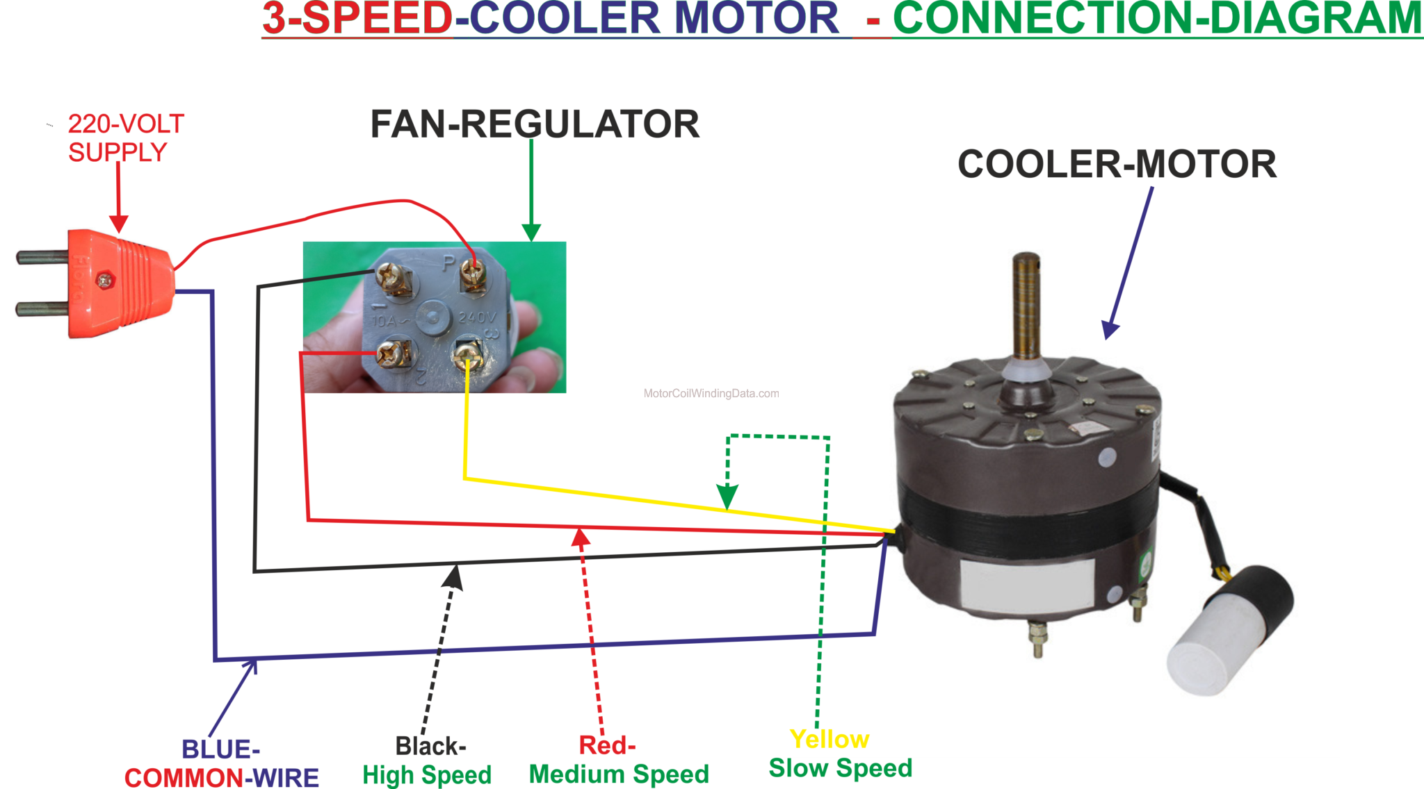
Cooler Switch Connection Diagram Wiring Diagram And Schematics

Schematic Swamp Cooler Switch Wiring Diagram An evaporative cooler switch wiring diagram is a schematic that shows the various connections and components of a switch used in an evaporative cooler. this diagram helps electricians and technicians understand how the switch should be wired and connected to the cooler’s motor and power source. Gather the necessary tools and materials. before starting the wiring process, make sure you have all the required tools and materials. this includes a screwdriver, wire strippers, electrical tape, wire nuts, and the evap cooler wiring diagram provided by the manufacturer. 2. turn off the power.

4 Wire Cooler Motor Connection Diagram Two Switch Wiring Conn 3 pin and 4 pin fan wire diagrams. 3 pin fan connections. *cable coloring varies from fan to fan. pin name. color. color. color. color. 1. Proper installation and wiring are essential for the optimal functioning of the evaporative cooler. the wiring diagram of an evaporative cooler includes various components that work together to ensure efficient cooling. these components include a motor, pump, thermostat, and junction box. the motor powers the fan, while the pump circulates. The 1 terminal is for the red wire that connects to the low power side of the blower. the 2 terminal is the connection point for the yellow wire going to the water pump power or hot terminal. the c connection is the black wire connecting to the blower for the high power connection. remember, the black wire or hot wire is the sensitive issue. The first step in wiring a 2 speed cooler motor is to gather all the necessary tools and materials. this typically includes wire strippers, electrical tape, wire nuts, and a wiring diagram for your specific motor model. the wiring diagram will provide a visual representation of how the wires should be connected, ensuring that you complete the.

Evaporative Cooler Switch Wiring Diagram The 1 terminal is for the red wire that connects to the low power side of the blower. the 2 terminal is the connection point for the yellow wire going to the water pump power or hot terminal. the c connection is the black wire connecting to the blower for the high power connection. remember, the black wire or hot wire is the sensitive issue. The first step in wiring a 2 speed cooler motor is to gather all the necessary tools and materials. this typically includes wire strippers, electrical tape, wire nuts, and a wiring diagram for your specific motor model. the wiring diagram will provide a visual representation of how the wires should be connected, ensuring that you complete the. A wiring diagram is a visual representation of the electrical connections and wiring layout of an evaporative cooler motor. this diagram provides a clear guide on how to properly wire and connect the different components of the motor, ensuring efficient and safe operation of the cooler. whether you are a diy enthusiast or a professional, this wiring diagram will help you understand the. Here are some steps to wire a walk in cooler: 1. plan the electrical layout. before starting the wiring process, it is crucial to plan the electrical layout of the walk in cooler. this includes determining the location of the power source, the placement of outlets, switches, and any other electrical components.

Cooler Switch Wiring Connection A wiring diagram is a visual representation of the electrical connections and wiring layout of an evaporative cooler motor. this diagram provides a clear guide on how to properly wire and connect the different components of the motor, ensuring efficient and safe operation of the cooler. whether you are a diy enthusiast or a professional, this wiring diagram will help you understand the. Here are some steps to wire a walk in cooler: 1. plan the electrical layout. before starting the wiring process, it is crucial to plan the electrical layout of the walk in cooler. this includes determining the location of the power source, the placement of outlets, switches, and any other electrical components.

Comments are closed.