Astable Multivibrator Using Ic 555 Circuit Working Waveforms

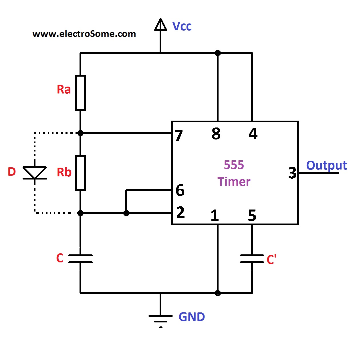
Astable Multivibrator Using Ic 555 Circuit Working Waveforms The schematic of the ic 555 as an astable multivibrator along with the three external components is shown below. ic 555 astable multivibrator circuit diagram: the pins 2 and 6 are connected and hence there is no need for an external trigger pulse. it will self trigger and act as a free running multivibrator (oscillator). The 555 ic can be used to create a free running astable oscillator to continuously produce square wave pulses. the 555 timer ic can be connected either in its monostable mode thereby producing a precision timer of a fixed time duration, or in its bistable mode to produce a flip flop type switching action. but we can also connect the 555 timer.

Astable Multivibrator Using 555 Timer Ic 555 timer astable multivibrator circuit diagram, waveforms and working is covered in this video.notes drive.google file d 10hu9ry6ybpcoqgbvt. 555 timer astable multivibrator circuit diagram. an astable multivibrator can be designed by adding two resistors (ra and rb in circuit diagram) and a capacitor (c in circuit diagram) to the 555 timer ic. these two resistors and the capacitor (values) are selected appropriately so as to obtain the desired ‘on’ and ‘off’ timings at the. 555 circuits part 1 – the fastest 555 oscillator. by varying the value of either r or c the 555 astable multivibrator circuit can be made to oscillate at any desired output frequency. but what is the maximum frequency of oscillations we can produce from a single 555 timer chip. to get the 555 to operate at its highest frequency in this 555. 555 timer astable multivibrator circuit diagram, waveforms and working is covered in this video.english video youtu.be 1ueabaltbmanotes d.

How Astable Multivibrator Using Ic 555 Works Detailed Study Basi 555 circuits part 1 – the fastest 555 oscillator. by varying the value of either r or c the 555 astable multivibrator circuit can be made to oscillate at any desired output frequency. but what is the maximum frequency of oscillations we can produce from a single 555 timer chip. to get the 555 to operate at its highest frequency in this 555. 555 timer astable multivibrator circuit diagram, waveforms and working is covered in this video.english video youtu.be 1ueabaltbmanotes d. Duty cycle %: (time high total time) * 100 = (t1 t) * 100 = (r1 r2) (r1 2*r2) *100. you can also use this 555 timer astable calculator to calculate the above values. you can also check out our article on the free running frequency of astable multivibrator to know more. here is the practical demonstration of the astable mode of 555 timer ic. The designing and working of astable multivibrator using a 555 timer ic is done by using ransistors and operational amplifiers. the 555 timer ic affords exact time delay from ms to hours. the oscillation frequency can be measured manually by small modification. 555 timer ic is a relatively cheap, stable and user friendly integrated circuit and.

Comments are closed.