Arduino Based Inverter Circuit

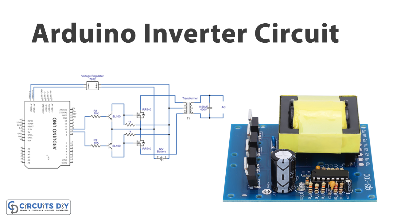
Arduino Inverter Circuit The above design is the recommended one! (just make sure to add the delay timer, as i have explained below!!) for the full program code please visit the following link: arduino spwm generator circuit. video clip. parts list. all resistors are 1 4 watt, 5% cfr. transformer = 9 0 9v 220v 120v current as per requirement. Author. pure sine wave inverter using arduino. inverter circuits are often needed where it is not possible to get ac supply from the grid. an inverter circuit is used to convert dc power to ac power and it can be divided into two types that is pure sine wave inverters or modified square wave inverters. these pure sine wave inverters are very.

Arduino Inverter Circuit How it works. as shown in the above figure, the working of this arduino based full bridge sinewave inverter can be understood with the help of the following points: the arduino is programmed to genearte appropriately formatted spwm outputs from pin#8 and pin#9. while one of the pins is generating the spwms, the complementary pin is held low. An arduino three phase inverter is a circuit which produces a 3 phase ac output through a programmed arduino based oscillator. in this post i have explained how to make a simple microprocessor arduino based 3 phase inverter circuit which could be upgraded as per user preference for operating a given 3 phase load. Step 1: making driver stage. the tasks that are performed in driver stage are generation of modified sine wave, monitoring the battery voltage, handling the other housekeeping tasks such as short circuit protection etc. here i have used an arduino nano to accomplish all these tasks. arduino is generating a modified sine waveform of 5v which is. Components used in single phase pure sine wave inverter using arduino. followings are the main components used in single phase pure sine wave inverter using arduino. i provided a brief explanation of each component below: arduino: arduino uno r3 is used to generate control signals for mosfet driver using spwm ( sinusoidal pulse width modulation.

Arduino Pure Sine Wave Inverter Circuit Step 1: making driver stage. the tasks that are performed in driver stage are generation of modified sine wave, monitoring the battery voltage, handling the other housekeeping tasks such as short circuit protection etc. here i have used an arduino nano to accomplish all these tasks. arduino is generating a modified sine waveform of 5v which is. Components used in single phase pure sine wave inverter using arduino. followings are the main components used in single phase pure sine wave inverter using arduino. i provided a brief explanation of each component below: arduino: arduino uno r3 is used to generate control signals for mosfet driver using spwm ( sinusoidal pulse width modulation. The arduino’s pwm frequency should be around 200 hz. if a 50 hz totem pole is set up on the arduino, the ic4047 can be eliminated and the signals can be directly linked to the left side terminals of r2 and r3. circuit for a 3 phase inverter using arduino. the pair of diagrams provided depict the setup of a 3 phase pwm controlled inverter that. The changes you will need to use this circuit for 220 are very straight forward: 1. you will need use a 220 volt inverter transformer instead of 110 volts. 2. you will need to set up the interrupt timer for 256 * 50 hz instead of 256* 60 hz. to do that, change the timer in setup to the code below. 3.

Arduino 3 Phase Inverter Circuit With Code Homemade Circuit Projects The arduino’s pwm frequency should be around 200 hz. if a 50 hz totem pole is set up on the arduino, the ic4047 can be eliminated and the signals can be directly linked to the left side terminals of r2 and r3. circuit for a 3 phase inverter using arduino. the pair of diagrams provided depict the setup of a 3 phase pwm controlled inverter that. The changes you will need to use this circuit for 220 are very straight forward: 1. you will need use a 220 volt inverter transformer instead of 110 volts. 2. you will need to set up the interrupt timer for 256 * 50 hz instead of 256* 60 hz. to do that, change the timer in setup to the code below. 3.

Comments are closed.