An Arduino Power Inverter Hackaday

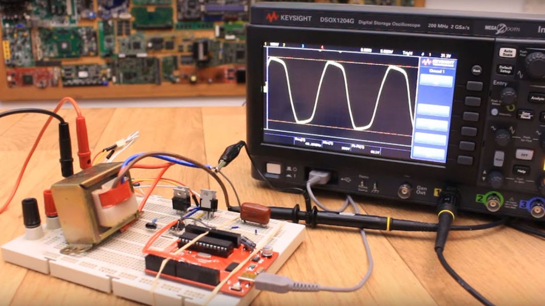
An Arduino Power Inverter Hackaday An arduino power inverter. if you’ve got a few solar panels lying around, or even if you want some 120 230 v ac power from a few 12 volt batteries, you’ll need a power inverter. sure, you can. The project is simplified by the use of a stm32f407 board which has some nice high speed a d as well as a ti h bridge board. another simplification was the use of a transformer, so the inverter.

Variable Power Supply Arduino Compatible Hackaday Io Posted in arduino hacks tagged 12 volt, arduino, inverter, power inverter hackaday links: december 3, 2011 december 3, 2011 by brian benchoff 35 comments. Description. the attiny212 412 based usb power delivery inverter converts direct current from usb pd power supplies into sine wave alternating current with selectable voltage and adjustable frequency. for this purpose, the attiny's powerful timer counter d (tcd) controls an h bridge with a subsequent low pass filter. R arduino • arduino finally released a board with esp32 mcu. arduino nano was always my favourite breadboard board and now we have nano esp32. i made this test sketch to test the speed and performance of this new board. you can find code and whole video in comments. Inverter arduino code. arduino. complete code of the driver stage. 1 #include "timerone.h" include timerone.h 2 #define. 3 low battery voltage 10.2 define high battery voltage limit as 14.2 4 #define. 5 high battery voltage 14.4 define low battery voltage limit as 10.2 6 int. 7 dutycycle = 0; initailize duty cylce variable as.

Diy Sinusoidal Power Inverter With Arduino By Jeremy S Cook R arduino • arduino finally released a board with esp32 mcu. arduino nano was always my favourite breadboard board and now we have nano esp32. i made this test sketch to test the speed and performance of this new board. you can find code and whole video in comments. Inverter arduino code. arduino. complete code of the driver stage. 1 #include "timerone.h" include timerone.h 2 #define. 3 low battery voltage 10.2 define high battery voltage limit as 14.2 4 #define. 5 high battery voltage 14.4 define low battery voltage limit as 10.2 6 int. 7 dutycycle = 0; initailize duty cylce variable as. Step 2: making power stage. as the inverter output power is 600va and it is 75% efficient so the input current at full load comes out to be 75amp approx. (using ohm's law) now this current amplification task is performed by the power stage . in this stage two n mosfets are configured in push pull topology to amplify the current. This project by electronoobs, however, introduces a new related concept called spwm — or sinusoidal pulse width modulation — then applies it to create a power inverter. in this setup, sinusoidally varying pulse width values are produced by an arduino board, which produces one side of an ac signal. a second signal is then added that outputs.

Gallery Arduino Mega2560 Powermeter Hackaday Io Step 2: making power stage. as the inverter output power is 600va and it is 75% efficient so the input current at full load comes out to be 75amp approx. (using ohm's law) now this current amplification task is performed by the power stage . in this stage two n mosfets are configured in push pull topology to amplify the current. This project by electronoobs, however, introduces a new related concept called spwm — or sinusoidal pulse width modulation — then applies it to create a power inverter. in this setup, sinusoidally varying pulse width values are produced by an arduino board, which produces one side of an ac signal. a second signal is then added that outputs.

Comments are closed.