963 3 Phase Uvw Arduino Code Part 1

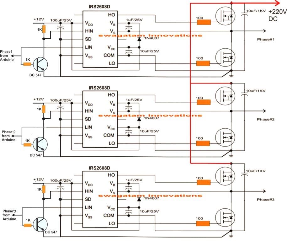
963 3 Phase Uvw Arduino Code Part 1 Youtube In this video number {963} 3 phase uvw inverter arduino code, part 1. i demonstrated how to write arduino code to generate three phase uvw phase signal to dr. The following diagrams are designed to work as a 3 phase pwm controlled inverter from an arduino. the first diagram is wired using six not gates from the ic 4049. this stage is used for bifurcating the arduino pwm pulses into complementary high low logic pairs so that the a bridge 3 phase inverter driver ic ic irs2330 can be made compatible.

3 Phase Motor Connections Uvw Electrical Wiring Work Hello everyone! i have a vsi spwm inverter project, but my supervisor ask me to upgrade it to a vfd inverter. i've found a code about how to generate 3 phase spwm in this article. it provides 6 spwm outputs, and i think i need to invert 3 spwm output to negative signals. then someone told me that i can invert the lookup table or pwm, so the output will act as negative signals, but the other. Advantages of 3 phase inverter. a 3 phase inverter circuit provides more efficient power than a single phase inverter. this is a very less cost project. there is no need to buy 3 phase transformer, which is very expensive. the circuit is very easy to design. arduino code. download this code from here. Void setup () {. put your setup code here, to run once: pinmode (mosfet1, output); sets digital pin as output. pinmode (mosfet3, output); sets digital pin as output. pinmode (mosfet5, output); sets digital pin as output. } void loop () {. put your main code here, to run repeatedly:. Example: x=round (0.8 * sinpwm [i]). the factor, 0.8 in this example, you can of course replace by a variable which value is derived from an analogread () of a pin connected to a potmeter or some sensor. but make sure to convert it to a value in the range 0 1 before you use it in the calculation. share.

Arduino 3 Phase Inverter Circuit With Code Homemade Circuit Projects Void setup () {. put your setup code here, to run once: pinmode (mosfet1, output); sets digital pin as output. pinmode (mosfet3, output); sets digital pin as output. pinmode (mosfet5, output); sets digital pin as output. } void loop () {. put your main code here, to run repeatedly:. Example: x=round (0.8 * sinpwm [i]). the factor, 0.8 in this example, you can of course replace by a variable which value is derived from an analogread () of a pin connected to a potmeter or some sensor. but make sure to convert it to a value in the range 0 1 before you use it in the calculation. share. Inverter arduino code. arduino. complete code of the driver stage. 1 #include "timerone.h" include timerone.h 2 #define. 3 low battery voltage 10.2 define high battery voltage limit as 14.2 4 #define. 5 high battery voltage 14.4 define low battery voltage limit as 10.2 6 int. 7 dutycycle = 0; initailize duty cylce variable as. All three bridge should be operate such that all of them should be 120 degree out of phase with each other. three phase sine wave inverter is designed using arduino microcontroller. arduino is used to generate spwm singals to drive gate driver circuits as shown in figure below. these spwm signal are 120 degree out of phase with each other.

Arduino 3 Phase Inverter Circuit With Code Homemade Circuit Projects Inverter arduino code. arduino. complete code of the driver stage. 1 #include "timerone.h" include timerone.h 2 #define. 3 low battery voltage 10.2 define high battery voltage limit as 14.2 4 #define. 5 high battery voltage 14.4 define low battery voltage limit as 10.2 6 int. 7 dutycycle = 0; initailize duty cylce variable as. All three bridge should be operate such that all of them should be 120 degree out of phase with each other. three phase sine wave inverter is designed using arduino microcontroller. arduino is used to generate spwm singals to drive gate driver circuits as shown in figure below. these spwm signal are 120 degree out of phase with each other.

3 Phase Variable Frequency Drive Circuit Diagram

Comments are closed.