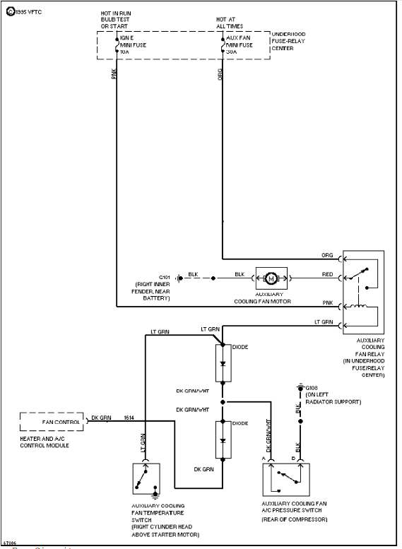
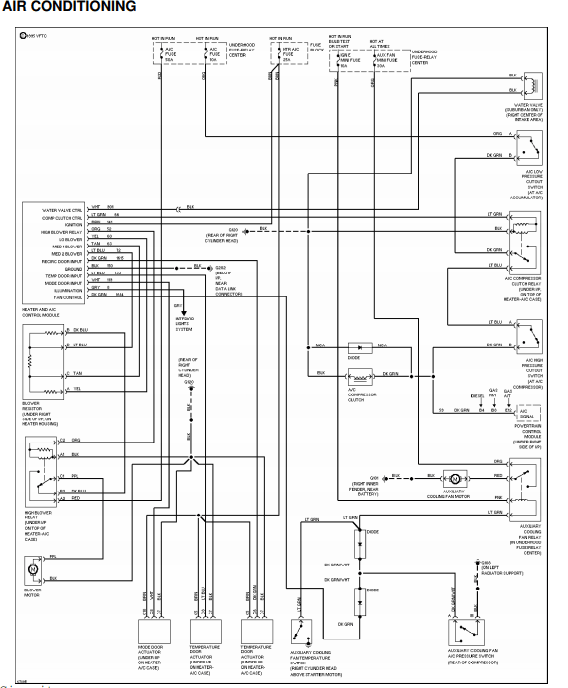
2000 Tahoe 5 3 Wiring Cooling Fan Diagram

Wiring Diagram 2000 Chevy Tahoe There are 9 components participating in the 5.3 vortec cooling system. these are the radiator, the upper and lower hose for the radiator, cap or pressure release valve, a water pump, a coolant thermostat, the thermostat housing, and a cooling fan shroud. 5.3 vortec cooling system diagram. the in depth discussion on all parts marked as a, b, c. The cooling system in a 5.3 vortec engine is made up of several different components, all working together to keep your engine at its optimal operating temperature. the main component is the radiator, which transfers heat from the engine coolant to the air outside of the vehicle. the radiator is usually located in front of the engine, where it.

Chevrolet Tahoe Wiring Diagrams Car Electrical Wiring Diagram Cut the ring terminal off the red wire from the relay harness and strip back the insulation. strip the insulation off both ends of the extra piece of wire listed in the parts list . put a 4 inch section of heat shrink over the red wire above where you will splice. now splice the red wire to the fan power wire. the dorman had a blue positive wire. Thread starter. itrader: ( 4 ) join date: feb 2008. location: arizona. posts: 2,079. likes: 1. received 8 likes on 7 posts. 5.3 wiring harness wiring diagrams here!!! thanks to my man mark west for hooking this up for me these are fuseblock and pcm and other essential wiring diagrams. September 7, 2022. the 5.3 vortec cooling system diagram is a helpful tool when it comes to understanding how this type of engine works. the diagram shows all of the different parts of the cooling system and how they are interconnected. it is important to note that the water pump is responsible for circulating coolant throughout the engine. Tahoe air conditioning wiring diagram. tahoe anti lock circuit diagram. tahoe anti lock circuit diagram. tahoe cooling fan circuit diagram. tahoe cooling fan circuit diagram. tahoe cruise control 5,7l wiring diagram. tahoe cruise control 5,7l wiring diagram. tahoe defogger schematics. tahoe defogger schematics.

Diagram Wiring Diagram For 2000 Tahoe Mydiagram Online September 7, 2022. the 5.3 vortec cooling system diagram is a helpful tool when it comes to understanding how this type of engine works. the diagram shows all of the different parts of the cooling system and how they are interconnected. it is important to note that the water pump is responsible for circulating coolant throughout the engine. Tahoe air conditioning wiring diagram. tahoe anti lock circuit diagram. tahoe anti lock circuit diagram. tahoe cooling fan circuit diagram. tahoe cooling fan circuit diagram. tahoe cruise control 5,7l wiring diagram. tahoe cruise control 5,7l wiring diagram. tahoe defogger schematics. tahoe defogger schematics. I installed 2006 e fans on my 2001. this is a step by step tutorial on how to upgrade any 99 02 gmt800 truck or suv to the 05 06 gmt800 electric cooling fans. this same setup can be used on 03 04 trucks as well, however, the only difference is the wiring that connects to the pcm. i will also add that a custom tune from someone like blackbear. Fan control relay. pin 30 to negative side of low speed fan. pin 85 ign power. pin 86 ecm x1 harness pin 17. pin 87 to ground. pin 87a to positive side of high speed fan. with the requested information above i'll be able to wire up the fans to the factory location and put together a write up on how to do the install.

Tahoe Wiring Schematic I installed 2006 e fans on my 2001. this is a step by step tutorial on how to upgrade any 99 02 gmt800 truck or suv to the 05 06 gmt800 electric cooling fans. this same setup can be used on 03 04 trucks as well, however, the only difference is the wiring that connects to the pcm. i will also add that a custom tune from someone like blackbear. Fan control relay. pin 30 to negative side of low speed fan. pin 85 ign power. pin 86 ecm x1 harness pin 17. pin 87 to ground. pin 87a to positive side of high speed fan. with the requested information above i'll be able to wire up the fans to the factory location and put together a write up on how to do the install.

Comments are closed.