Cantilever Beam Section

What Is The Cantilever Beam Advantages And Disadvantages Engineering Example cantilever beam with single load at the end, metric units. the maximum moment at the fixed end of a ub 305 x 127 x 42 beam steel flange cantilever beam 5000 mm long, with moment of inertia 8196 cm 4 (81960000 mm 4), modulus of elasticity 200 gpa (200000 n mm 2) and with a single load 3000 n at the end can be calculated as. The bending moment at a given section of a cantilever beam is the sum of moments about the section of all the loads acting between the section and the free end. consider a cantilever beam ab of length 'l' subjected to a point load 'w' at the end b. a section x x at a distance 'x' from the free end b is placed.

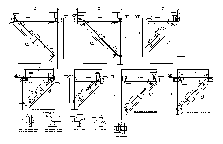
Steel Cantilever Beam Section Cad Drawing Download Dwg File Cadbull A cantilever beam is a structural element that extends horizontally and is supported on only one end. the unsupported end is known as the cantilever, and it extends beyond the support point. cantilever beams are often used in construction to support balconies, roofs, and other overhangs. they can also be used in bridges and other structures to. A cantilever beam is a rigid bar or beam whose one end is free while the other end is fixed to a support (usually a vertical wall or structure). the load acting on the beam’s free end creates a bending moment and reaction force on the fixed end. the cantilever beams serve to produce a bending effect within specific limits. 1.as for the point load, we first calculate the reaction forces v a, h a and moment m a in the determinate structure – cantilever beam – due to the equilibrium conditions. line load applied on cantilever beam. ∑ h = 0: h a = 0. ∑ v = 0: v a – 14.1 k n m ⋅ 1.0 m = 0 > v a = 14.1 k n. The cantilever beam is one of the most simple structures. it features only one support, at one of its ends. the support is a, so called, fixed support that inhibits all movement, including vertical or horizontal displacements as well as any rotations. the other end is unsupported, and therefore it is free to move or rotate.

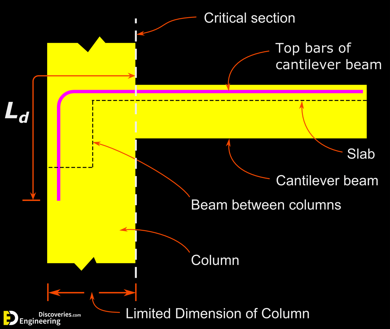
Design Of Cantilever Beam Reinforcement Details Basic Rules To 1.as for the point load, we first calculate the reaction forces v a, h a and moment m a in the determinate structure – cantilever beam – due to the equilibrium conditions. line load applied on cantilever beam. ∑ h = 0: h a = 0. ∑ v = 0: v a – 14.1 k n m ⋅ 1.0 m = 0 > v a = 14.1 k n. The cantilever beam is one of the most simple structures. it features only one support, at one of its ends. the support is a, so called, fixed support that inhibits all movement, including vertical or horizontal displacements as well as any rotations. the other end is unsupported, and therefore it is free to move or rotate. The shear stress at any given point y 1 along the height of the cross section is calculated by: where i c = b·h 3 12 is the centroidal moment of inertia of the cross section. the maximum shear stress occurs at the neutral axis of the beam and is calculated by: where a = b·h is the area of the cross section. This section will demystify these concepts and shed light on why cantilever beams are both structurally sound and aesthetically captivating. basic concepts of a cantilever beam before diving deeper into the mechanics and applications of cantilever beams, it’s crucial to establish a solid understanding of their basic components and terminology.

Figure 1a Shows The Cantilever Beam And Figure 1b Shows The Cross The shear stress at any given point y 1 along the height of the cross section is calculated by: where i c = b·h 3 12 is the centroidal moment of inertia of the cross section. the maximum shear stress occurs at the neutral axis of the beam and is calculated by: where a = b·h is the area of the cross section. This section will demystify these concepts and shed light on why cantilever beams are both structurally sound and aesthetically captivating. basic concepts of a cantilever beam before diving deeper into the mechanics and applications of cantilever beams, it’s crucial to establish a solid understanding of their basic components and terminology.

Design Of Cantilever Beam How To Design A Rcc Cantilever Beam

Comments are closed.